欢迎光临!1kic网专注于为电子元器件行业提供免费及更实惠的芯片ic交易网站。
infineon公司的IPW60R080P7是CoolMOS™第七代平台, 600V CoolMOS™ P7高压功率晶体管,采用超级结(SJ)原理和Infineon开拓的技术,组合了快速开关SJ MOSFET和极容易使用如非常低的激励电路趋向,体二极管对抗硬交换的杰出鲁棒性和极好的ESD能力.此外,极好的低开关和导通损耗使得开关应用变得更有效率,更加紧凑和更加凉爽.本文介绍了采用CoolMOS™ P7超级结MOSFET的2kW高效工业电池48V充电器参考设计主要特性,包括有电池温度监测器,当输入小于127V AC时自动配置输出功率到1000W,用于并联应用的RS485总线通信,多种颜色LED指示器,用来标示电池状态,充电,误差和故障,集成了电池管理系统(BMS),以及短路保护,反向极性保护,AC电压过压和欠压保护,不用外接融丝的过热保护和自动重置以及用于电池的热探针.主要用在电动自行车电池充电器,电动摩托车电池充电器和电动车电池充电器.本文介绍了IPW60R080P7主要特性和优势以及最大指标,以及工业电池48V充电器参考设计主要特性,电源板和控制板电路图,材料清单和PCB设计图.
The CoolMOS™ 7th generation platform is a revolutionary technology for high voltage power MOSFETs, designed according to the superjunction (SJ) principle and pioneered by Infineon Technologies. The 600V CoolMOS™ P7 series is the successor to the CoolMOS™ P6 series. It combines the benefits of a fast switching SJ MOSFET with excellent ease of use, e.g. very low ringing tendency, outstanding robustness of body diode against hard commutation and excellent ESD capability.
Furthermore, extremely low switching and conduction losses make switching applications even more efficient, more compact and much cooler.
IPW60R080P7主要特性:
• Suitable for hard and soft switching (PFC and LLC) due to an outstanding commutation ruggedness
• Significant reduction of switching and conduction losses
• Excellent ESD robustness >2kV (HBM) for all products
• Better RDS(on)/package products compared to competition enabled by a low RDS(on)*A (below 1Ohm*mm²)
• Fully qualified acc. JEDEC for Industrial Applications
IPW60R080P7优势:
• Ease of use and fast design-in through low ringing tendency and usage across PFC and PWM stages
• Simplified thermal management due to low switching and conduction losses
• Increased power density solutions enabled by using products with smaller footprint and higher manufacturing quality due to >2 kV ESD protection
• Suitable for a wide variety of applications and power ranges
IPW60R080P7潜在应用:
PFC stages, hard switching PWM stages and resonant switching stages for e.g. PC Silverbox, Adapter, LCD & PDP TV, Lighting, Server, Telecom and UPS.
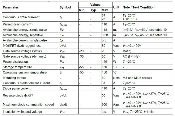
IPW60R080P7最大指标:
采用CoolMOS™ P7超级结MOSFET的2kW高效工业电池48V充电器参考设计
This document presents design considerations and results from testing a 2 kW industrial battery charger that is capable of charging 48 V based lead-acid and Li-ion batteries. The design is based on a dual-boost PFC and a half-bridge LLC DC-DC power supply solution, with natural convection cooling, using:
600 V CoolMOS™ P7 superjunction (SJ) MOSFETs for hard-switching and soft-switching topologies
IDH16G65C6 CoolSiC™ Schottky diode 650 V G6 for an attractive price-performance ratio
BSC030N08NS5 OptiMOS™ 5 80 V power MOSFET for reverse polarity protection
IDB15E60 600 V silicon power diode
ICE3PCS01G PFC controller IC for active Continuous Conduction Mode (CCM) power
ICE2HS01G resonant mode controller
ICE5QR2280AZ CoolSET™ QR Flyback controller
2EDN7524F EiceDRIVER™ 2EDN family of non-isolated dual gate drivers
IRS21814 600 V high- and low-side gate driver IC
XMC1403-Q064X0200 AA 32-bit XMC1000 industrial microcontroller
This application note provides a detailed description of the main features and operation under both steady-state and abnormal operating conditions of a 2 kW highly efficient natural convection-cooled industrial battery charger for 48 V lead-acid and Li-ion batteries. This demo board solidly confirms how different Infineon Technologies devices, ranging from power semiconductors to the controllers for the internal converters as well as for the accurate charging profile, perfectly fit a range of industrial applications.
工业电池48V充电器参考设计主要特性:
Different battery types (chemistries) can be charged, as explained in section 3.1.
Different battery charging capacities can be selected, as indicated in Table 4.
Clear signalization of the operation status of the charger during normal operation, as described in section 3.3, and when an error is present, as described in section 3.4.
Accurate charging profile according to the chemistry type selected as well as the measured temperature of the battery during the charging process, as described in the “Lead-acid and Li-ion charging profiles” section.
In case larger batteries need to be charged or faster charge capability is needed, the battery charger can be connected in parallel with another unit to achieve this. This operation is clearly explained in section 5.
High Power Factor (PF) and low Total Harmonic Distortion (THD) response at high-line, as shown in Figure 23.
Efficiency higher than 92 percent from 20 percent of the rated load (2 kW) upward when Vin = 230 V AC, and efficiency higher than 91 percent of the rated load (1 kW) upward when Vin = 90 V AC, during CCM.
High performance achieved by using Infineon Technologies best-in-class devices:
− TO-247 600 V CoolMOSTM P7 SJ MOSFETs for both dual-boost bridgeless PFC and half-bridge LLC topologies, along with single TO-220 650 V CoolSICTM sixth-generation Schottky diodes.
− EiceDRIVERTM 2EDN non-isolated gate driver as well as 600 V high- and low-side driver ICs.
− QR Flyback controller ICE5QR4780AZ CoolSET™.
− Super SO8 OptiMOS™ MOSFETs for battery management system control.
Robust and realiable operation under different abnormal conditions:
− Power Line Disturbance (PLD) events, like AC-Line Drop-Out (ACLDO) and voltage sag, as shown from Figure 30 to Figure 33.
− Surge events that do not represent a serious threat to the integrity of the industrial battery charger according to what it is specified in the Surge immunity (EN61000-4-5)Surge immunity (EN61000-4-5) test in section 8.6.
In case higher battery voltages are required, section 6 provides a list of changes that would be necessary to make at hardware level. Two different battery voltage ratings are considered: a) 72 V (range 67.2 V to 86.4 V at 30 A max.) and b) 144 V (range 134.4 V to 172.8 V at 15 A max.).
The 2 kW industrial battery charger offers a charging solution that operates on any single-phase 90 V AC to 265 V AC grid worldwide with a 94.7 percent peak efficiency. The charger has two charging profiles implemented: one for Li-ion batteries and the other for lead-acid batteries. The respective charging profiles correspond to the latest trends of battery charging. With the selectable nominal battery capacity (Cnom) feature, the charging current can be automatically adjusted in order to charge different battery sizes and amp-hour ranges to help customers achieve battery charging flexibility.
The charger is designed based on a dual-boost PFC that provides high PF of greater than 0.9 and meets PFC regulation as per IEC61000-3-2 Class A, followed by a converter stage realized by a half-bridge LLC configuration. Infineon’s latest 600 V CoolMOS™ P7 SJ MOSFET enables the design with natural convection cooling. The design has a battery management control system capable of charging both 48 V lead-acid and Li-ion batteries in the different charging modes – constant voltage and CCM.
The battery management control system implemented is designed to optimally charge lead-acid (WET, GEL, AGM, EFB and VRLA) as well as Li-ion (LiPo, Li2MnO3, Li2Mn2O4, Li4Ti5O12 and LiFePO4) batteries used on electric vehicles including E-scooters, E-bikes and low-speed vehicles. Furthermore, an RS485 bus communication protocol feature allows for a master/slave operation that can extract 4 kW max. charging power when connecting two chargers in parallel configuration, ensuring seamless power distribution and a fast charging feature for Li-ion batteries.
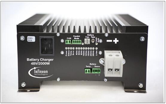
图1. 工业电池48V充电器参考设计外形图
Some of the main features are listed below:
Battery temperature monitor
Auto-configures output power to 1000 W when connected to less than 127 V AC to prevent nuisance breaker trips
RS485 bus communication for parallel operation
Multi-colored LED indicator for battery status, charging, error and fault indication
Convection cooled
Battery Management System (BMS) integration
Protected against short-circuit, reversed polarity, over- and under-AC-voltage, over-heating Without external fuses and with an automatic reset
Control of the charge time and automatic detection of faulty batteries
Thermal protection with internal probe
Thermal probe for battery
Dimensions: 258 × 123 × 80 mm
Weight: 7.5 kg
工业电池48V充电器参考设计特性应用:
E-bikes – pedelecs battery charger
E-rickshaws – E-scooters battery charger
Forklifts – E-carts battery charger
Micro E-cars – logistics EV battery charger
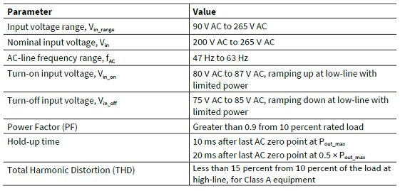
工业电池48V充电器参考设计输入特性:
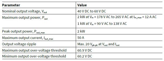
工业电池48V充电器参考设计输出特性:
工业电池48V充电器参考设计不同负载下的效率:
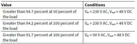

图2. 2kW工业电池48V充电器参考设计功能组块图
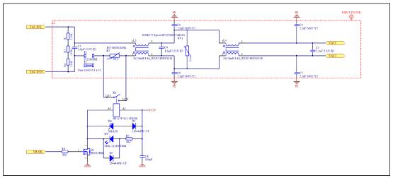
图3.两级EMI滤波器和浪涌限流电路

图4.两级升压半无桥PFC转换器电路
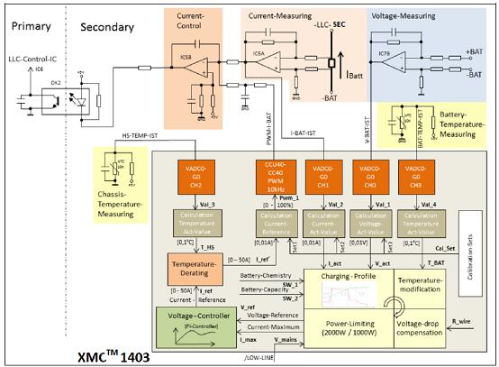
图5.LLC转换器和XMC微控制器间接口电路
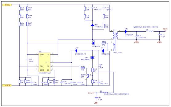
图6.辅助电源设计电路
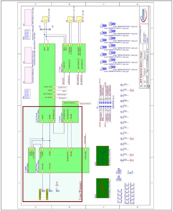
图7.主板框图
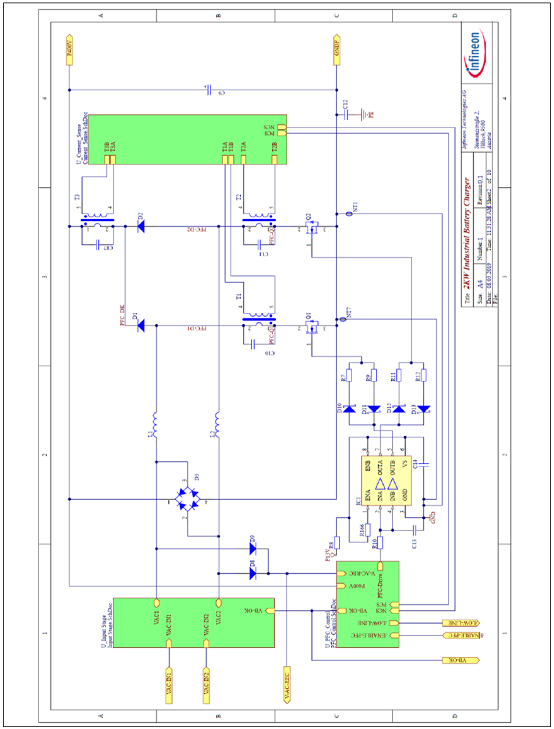
图8.带控制器接口的双PFC升压电路
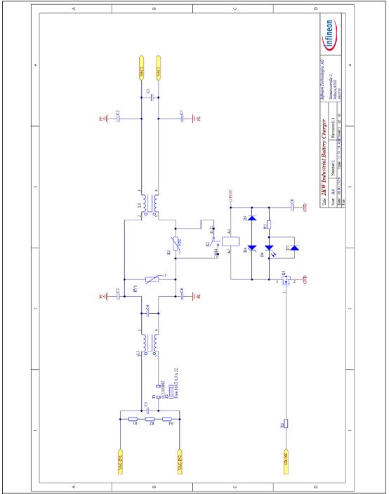
图9.EMI滤波器和浪涌电流限流电路图
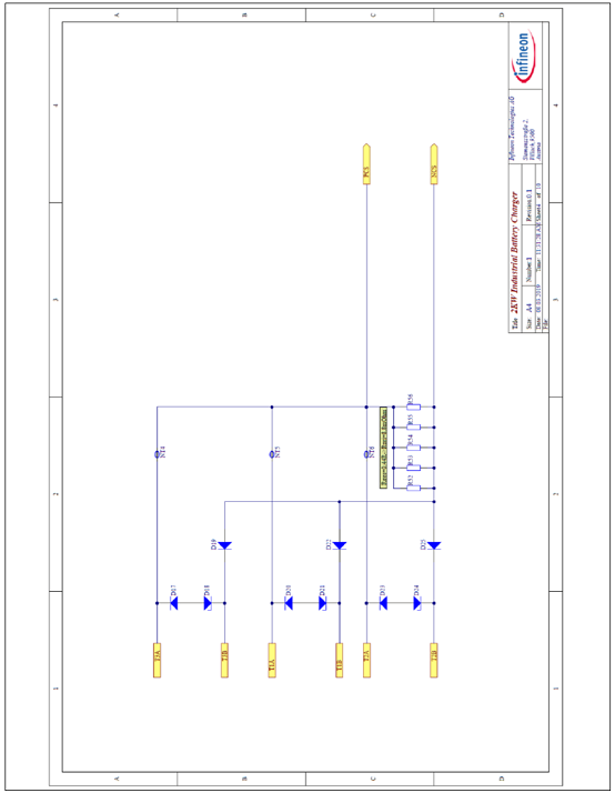
图10.用于PFC控制的电流变压器次级边检测电路
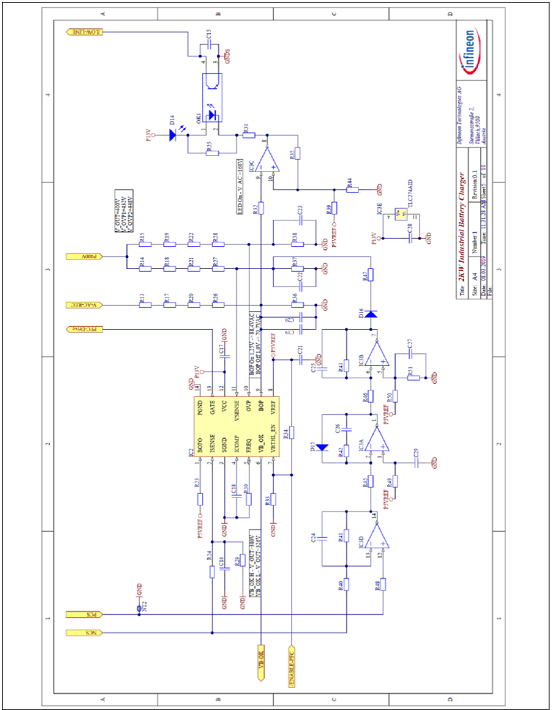
图11. PFC控制电路
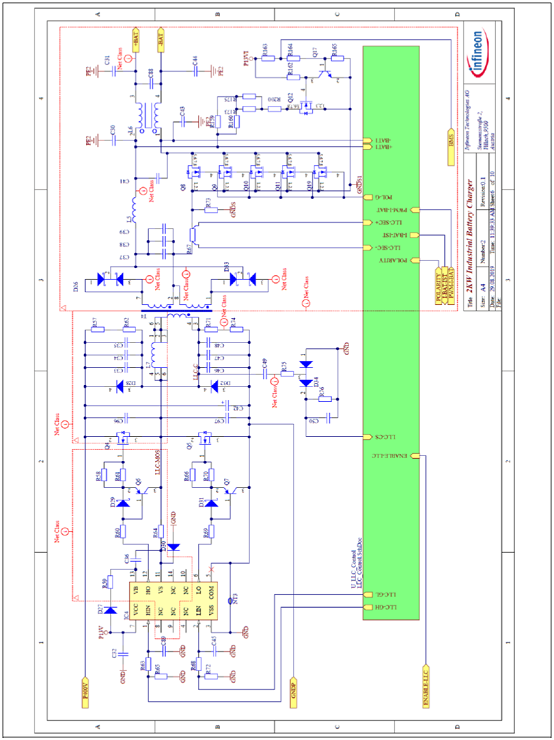
图12. LLC半桥转换器初级和次级电路与控制器接口电路
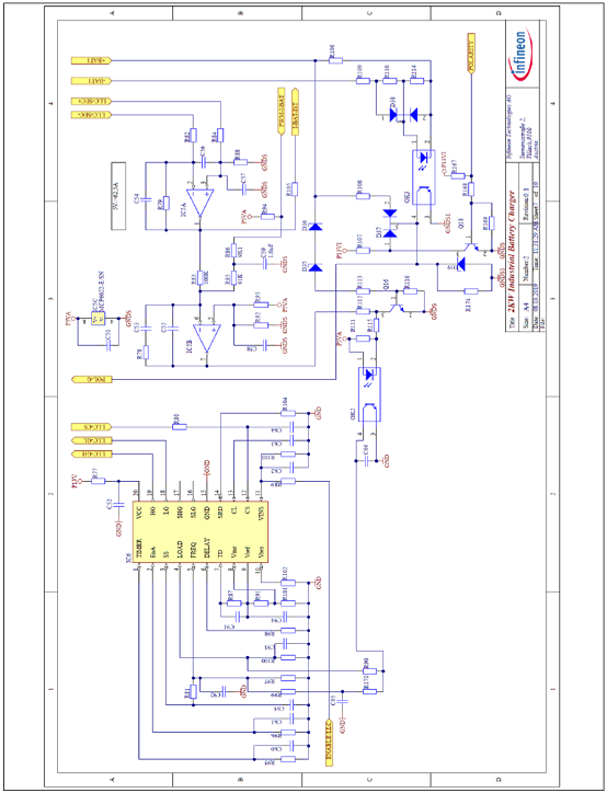
图13. 包括反馈回路控制电路的 LLC控制器电路
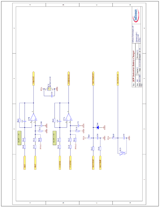
图14. 电池检测电路

图15. 偏压电源电路
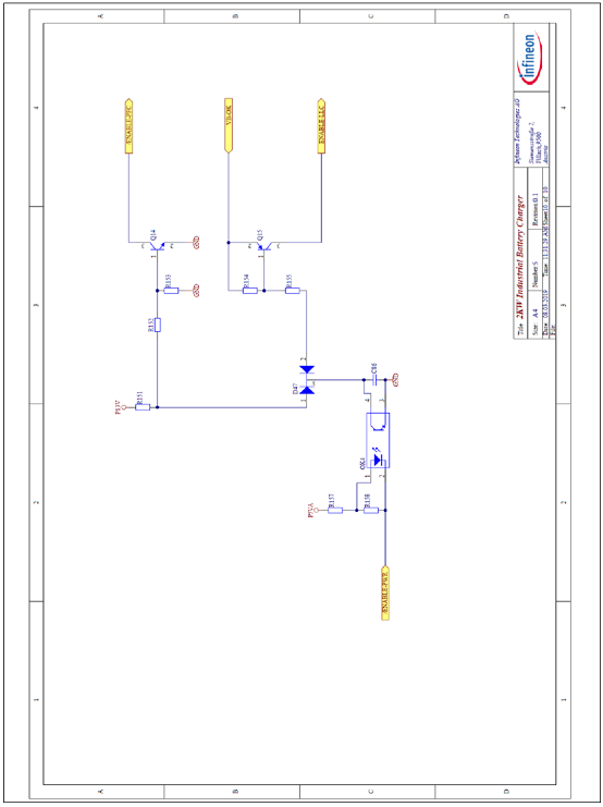
图16. 使能电路

图17. 工业电池48V充电器参考设计PCB设计图:顶层
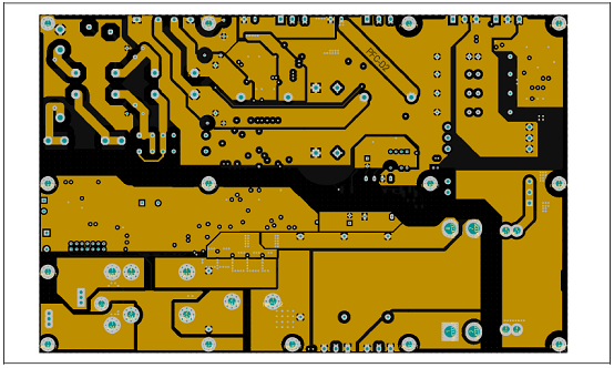
图18. 工业电池48V充电器参考设计PCB设计图:内1层

图19. 工业电池48V充电器参考设计PCB设计图:内2层
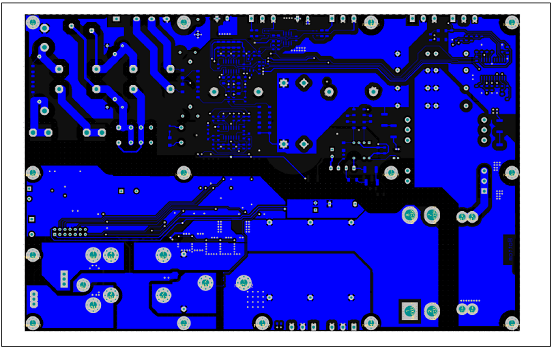
图20. 工业电池48V充电器参考设计PCB设计图:底层
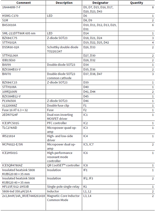
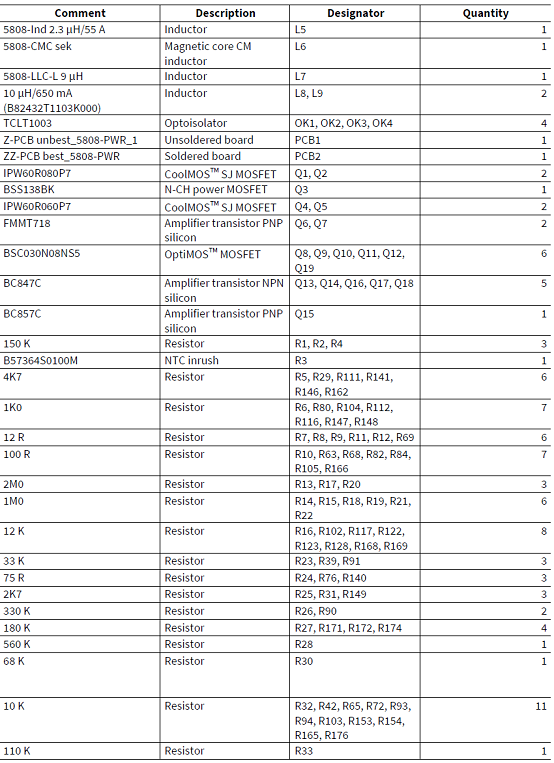
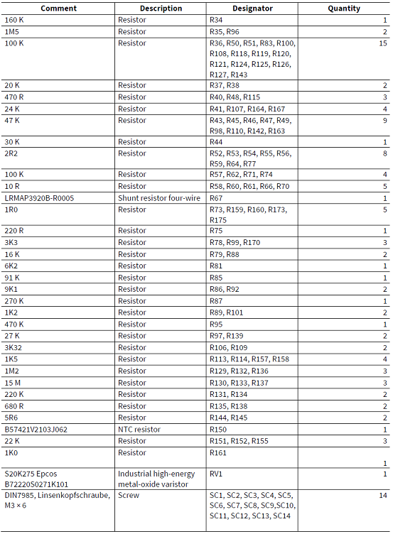
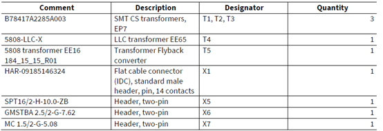
工业电池48V充电器参考设计电源板材料清单:

控制板电路图
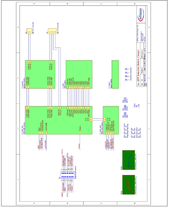
图21. 工业电池48V充电器参考设计控制板框图
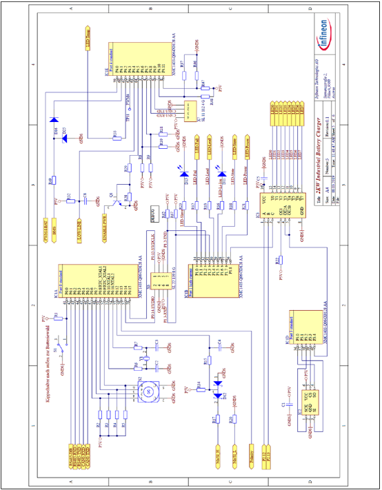
图22. 工业电池48V充电器参考设计控制板电路图:ADC相关电路

图23. 工业电池48V充电器参考设计控制板电路图:XMC微控制器输入电压电源
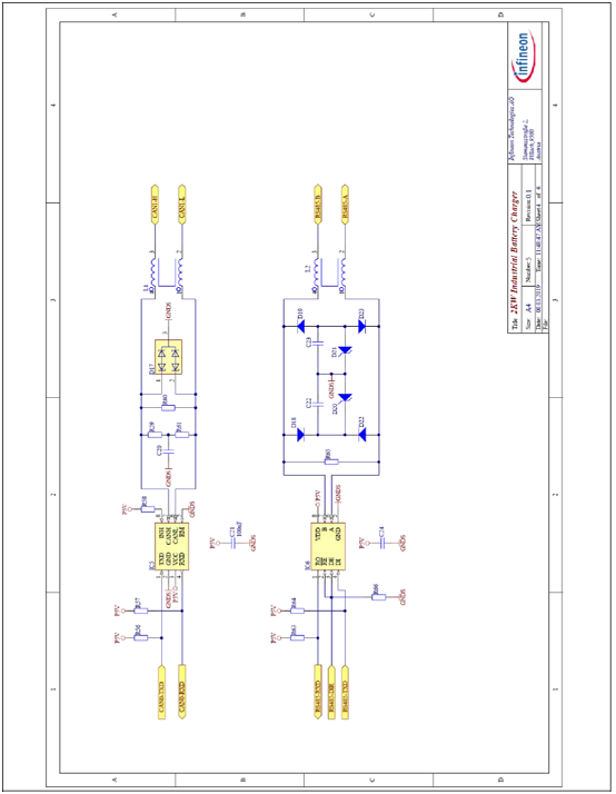
图24. 工业电池48V充电器参考设计控制板电路图:通信接口端口电路

图25. 工业电池48V充电器参考设计控制板电路图:基于主数字XMC1400的接口电路
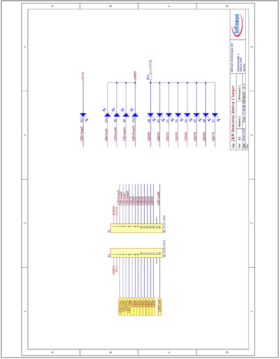
图26. 工业电池48V充电器参考设计控制板电路图:LED指示器电路
控制板PCB布局图
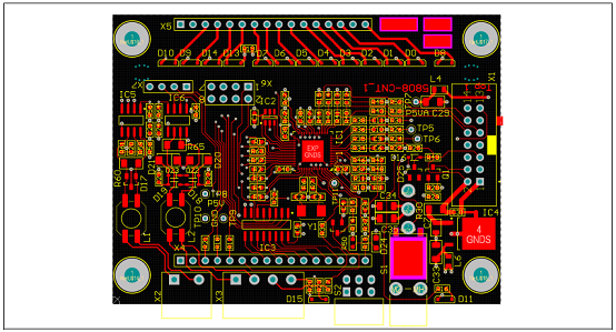
图27. 工业电池48V充电器参考设计控制板PCB设计图:顶层
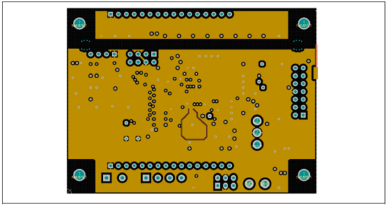
图28. 工业电池48V充电器参考设计控制板PCB设计图:内1层
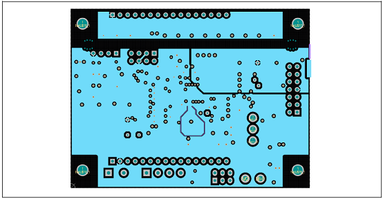
图29. 工业电池48V充电器参考设计控制板PCB设计图:内2层
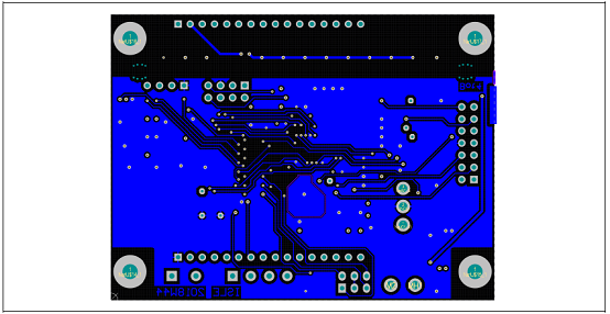
图30. 工业电池48V充电器参考设计控制板PCB设计图:底层
控制板材料清单:


详情请见:
https://www.infineon.com/dgdl/Infineon-IPW60R080P7-DS-v02_01-EN.pdf?fileId=5546d4625acbae4c015accfab2a0026a
和https://www.infineon.com/dgdl/Infineon-Applicationnote_EVAL_2KW_48V_CHAR_P7_2kw_battery_charger_CoolMOS-ApplicationNotes-v01_00-EN.pdf?fileId=5546d462696dbf120169ba1f4fa14b81
1kic网-首个免费IC网-电子元器件ic交易网-芯片集成电路代理商供应商查询